Segmental Structural Design and Construction Methodologies for Urban Elevated Running Corridors - Technology
Project Name : SUSTAINABLE URBAN ELEVATED ROAD CORRIDORS, RING ROAD, NEW DELHI
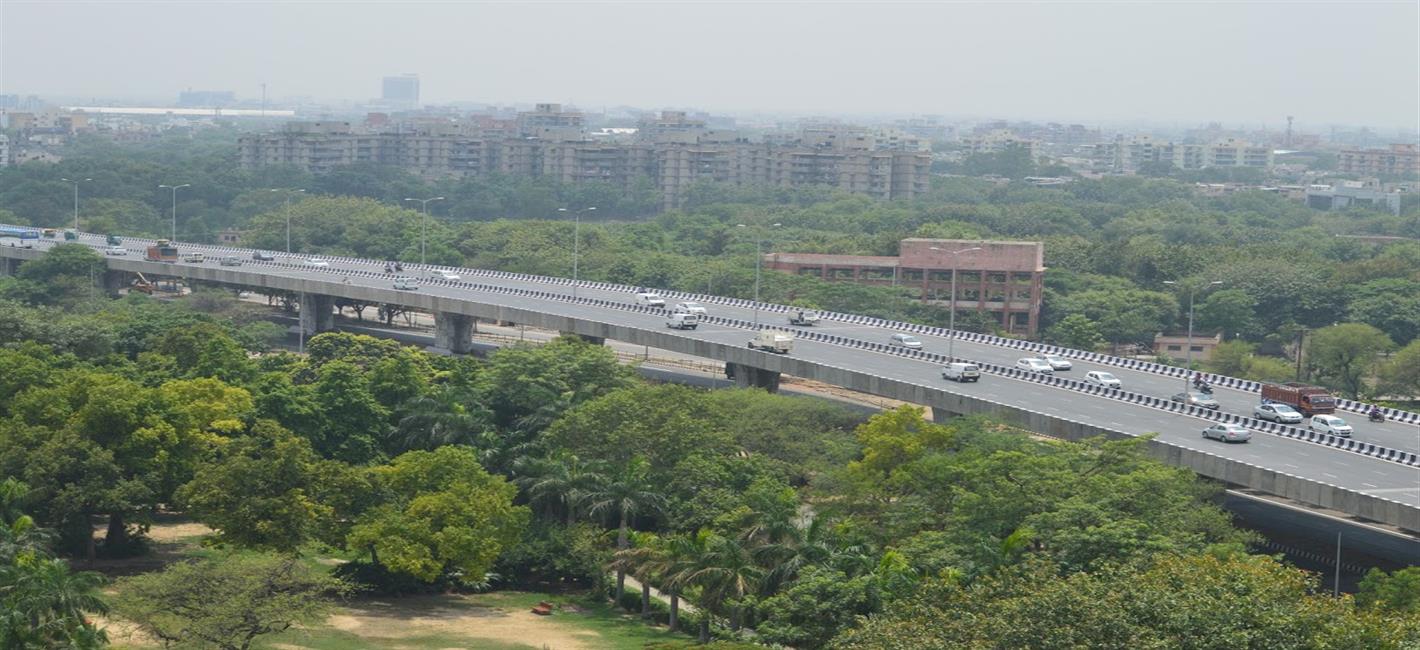
Delhi has maximum number of vehicles on its roads, more than the number of vehicles in other metropolitan cities, i.e., Kolkata, Mumbai and Chennai put together. This is largely because the booming growth of infrastructure combined with socio-economic growth in terms of employment opportunities, education and health care facilities, attracts streams of migrants to the Capital city. There are 7.5 million registered vehicles in the city, which is the highest in the world among all cities, most of which do not follow any pollution emission norm (within municipal limits), while the National Capital Region Delhi (NCR Delhi) has 11.2 million vehicles. It is estimated that Delhi and NCR lose nearly 42 crore (420 million) man-hours every month while commuting between home and office through public transport, due to the traffic congestion. The city planners and departments entrusted with creation of public transport infrastructure face the relentless challenge of allocating the rapidly shrinking scarce land resources for creation of assets like flyovers and underpasses. Shortage of land is forcing city planners to create infrastructure over the city drains, one recent example is that of the Barapullah Flyover created during the Common Wealth Games (CWG) in Delhi in the year 2010, despite strong objections by environmental experts. The quest for that elusive solution which would balance of the social, environmental, economic and sustainability issues. In this endeavor, The Publi
Delhi has maximum number of vehicles on its roads, more than the number of vehicles in other metropolitan cities, i.e., Kolkata, Mumbai and Chennai put together. This is largely because the booming growth of infrastructure combined with socio-economic growth in terms of employment opportunities, education and health care facilities, attracts streams of migrants to the Capital city. There are 7.5 million registered vehicles in the city, which is the highest in the world among all cities, most of which do not follow any pollution emission norm (within municipal limits), while the National Capital Region Delhi (NCR Delhi) has 11.2 million vehicles. It is estimated that Delhi and NCR lose nearly 42 crore (420 million) man-hours every month while commuting between home and office through public transport, due to the traffic congestion. The city planners and departments entrusted with creation of public transport infrastructure face the relentless challenge of allocating the rapidly shrinking scarce land resources for creation of assets like flyovers and underpasses. Shortage of land is forcing city planners to create infrastructure over the city drains, one recent example is that of the Barapullah Flyover created during the Common Wealth Games (CWG) in Delhi in the year 2010, despite strong objections by environmental experts. The quest for that elusive solution which would balance of the social, environmental, economic and sustainability issues. In this endeavor, The Publi
Lakh
Project Budget
01 Jan 2018
Start Date
01 Jan 2019
Completion Date
NEW DELHI
Location
Project Team / Contact Us
| S.No. | Name(Mr/Mrs) | Designation | Office Address | Office Number | Mobile Number | Email ID |
|---|---|---|---|---|---|---|
| 1 | Sarvagya Srivastava | E-in-C | ||||
| 2 | Manu Amitabh | Cpm | ||||
| 3 | Manoj Kumar | PM |
TECHNOLOGY
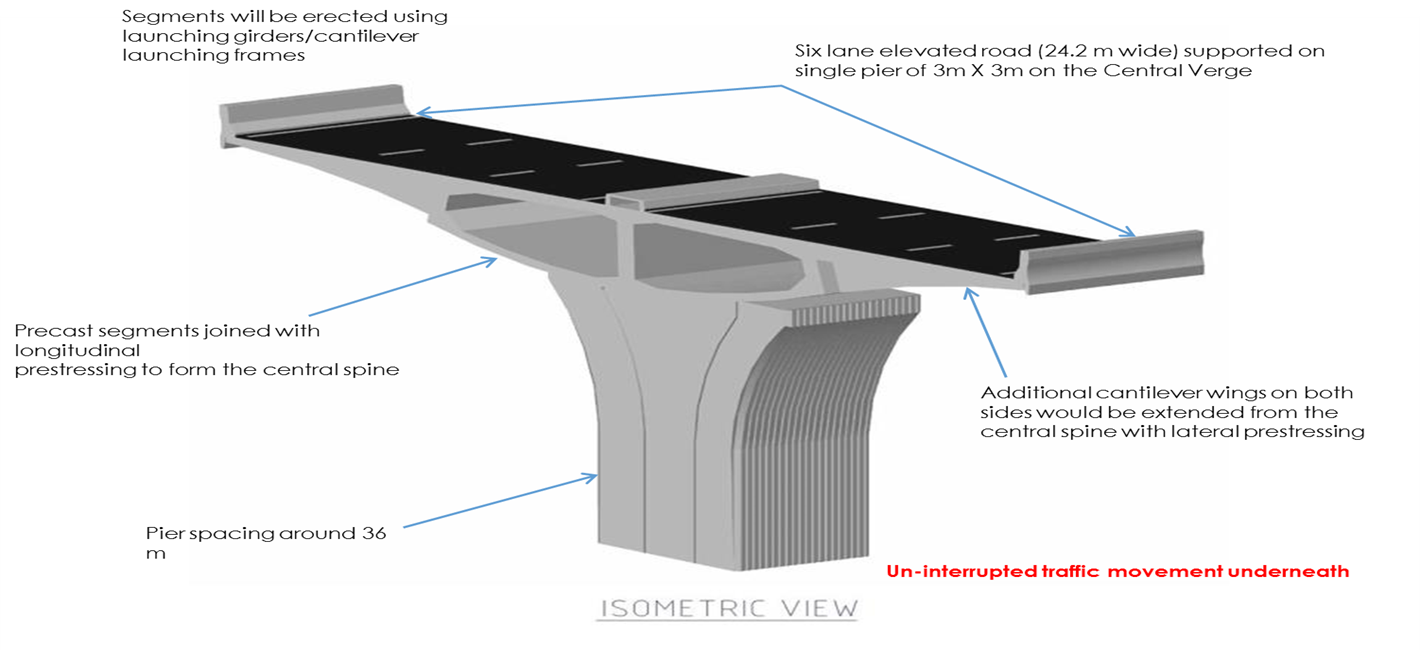
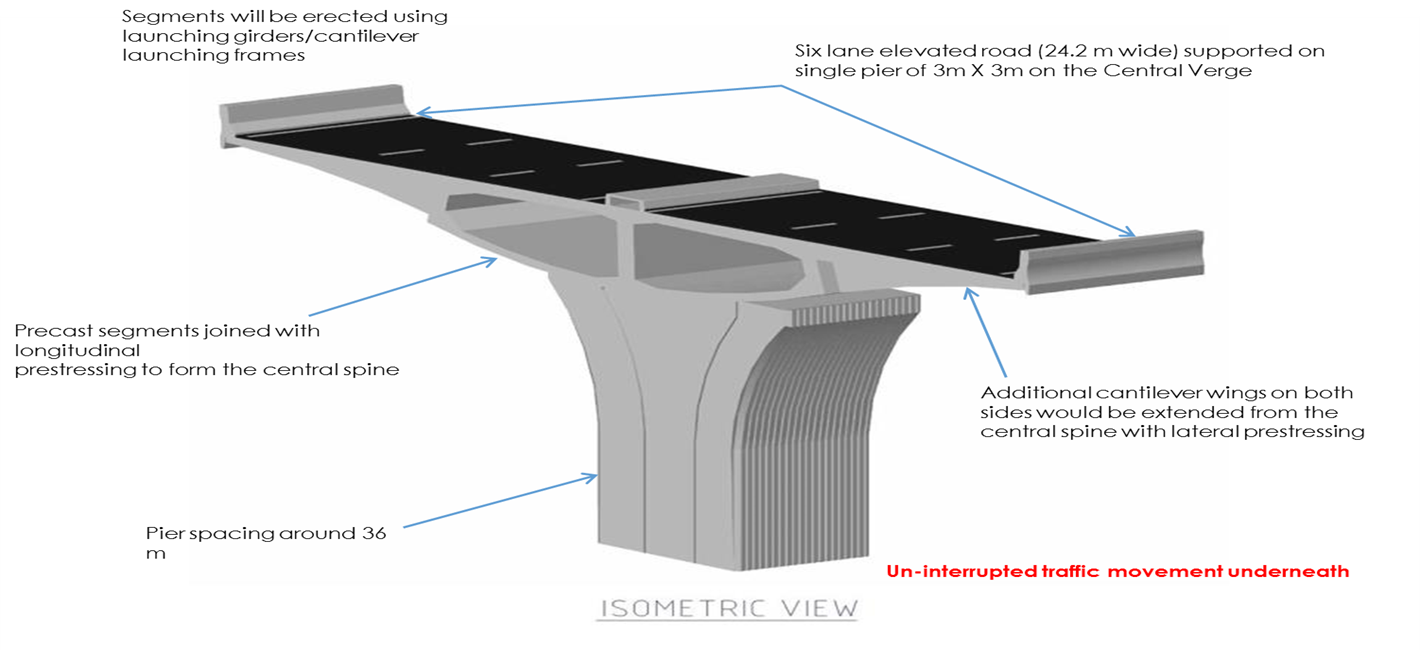
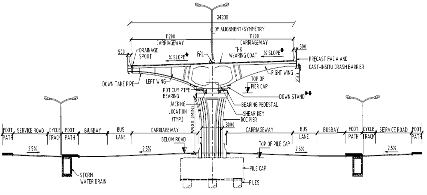
Structural system on single central verge piers, consisting of a longitudinally post-tensioned spine beam superstructure, with transversely post-tensioned wings put in place by an elaborate launching system, and later stitched, is devised.
The super-structure consists of the flyover deck of width 24.20m. The whole box girder is supported on single column. Since, transportation, erection of full box girder is not feasible without heavy launching girder and cranes, the superstructure is divided into three parts namely two cantilever slabs and two cell Box girder. The loads on cantilever slabs shall be transferred essentially to box girder from there to bearing thus to pier and foundations. For all longitudinal actions (longitudinal bending/shear force/torsion etc), are through central box girder only, thus it is called as Spine Beam.
The Spine Beam Superstructure is two cell box girders with inclined webs. The overall width of the spine beam is 6.0m at top. Cantilever Slabs (Wings) on either side are 9.10m each. The cantilever slab portion is provided with Ribs which are abutting to Spine beam Webs. These ribs essentially transfer the shear force from cantilever portion to spine beam; moreover, ribs in combination with top slab will act as “T” sections which are effective in transferring the cantilever bending moment by Strut (Rib portion) and Tie Action (top slab). The diaphragms are proposed at bearing location only; its thickness is 700mm.
The transverse spacing of bearing is 3.250m and the distance between the bearings in longitudinal direction is 1000mm from centre of the pier. The clear spacing between the diaphragms works out to be 1000m.
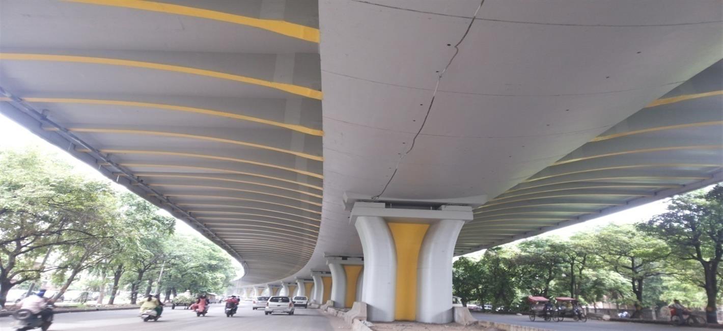
The sub-structure consists of Single column with “Dumble” shape in cross section with varying width is proposed from aesthetics point of view. Grooves of 25mm deep are provided on the surface to improve the aesthetics of the pier. The top width of the pier is restricted to 4.50m (H) and 3.20m (L) in longitudinal direction. The Vertical Clearance of 5.5m is measured on roadside beyond vertical plane drawn on outer face of crash barrier, i.e., with horizontal clearance of 0.5m from outer face of pier.
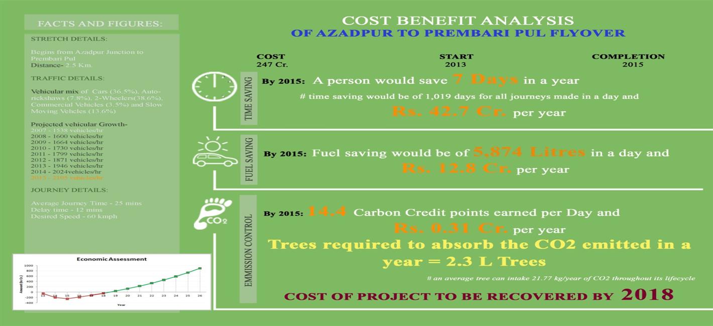
A cost-benefit analysis was done for all elevated corridors under construction. To project the extent of reduction in travel time/idling time and associated savings of man hour, fuel consumption and reduced emissions over the short term period of 7 years 2009-15 , the following assumptions/ calculations were made:
- Total volume of traffic at different points of time was computed assuming increase in traffic at the rate of 4% per annum(even though traffic in Delhi is growing at a much higher rate); Idling/waiting time and average speed of traffic before and after construction was based on actual traffic surveys;
- For monetising saving of man hour, average income of Rs 15,000 per month has been assumed ( per capita income in Delhi is Rs. 2.01 lakh per year in 2012-13 according to Economic Survey tabled in Delhi Assembly).
- Cost of fuel has been worked out at prevailing price; and
- Inflation at the rate of 7% per annum.
- To compensate for the maintenance costs that would be incurred after 5 years of the commissioning of the projects, for all projections beyond 2015, nil increment in traffic volumes and inflation has been assumed.
The summary of the findings of the study, for one of the elevated corridor projects i.ePrembariPul to Azadpur is presented in a fact-sheet in Figure 9. It was found that the cost of the 1.32 Km elevated corridor (total length of corridor improvement is 2.5 Kms) would be recovered in 3 years.
Overall, for all the four stretches combined, lot of benefits will accrue to the citizens of Delhi in terms of savings of time, fuel and a huge reduction in pollution. As per the study for all the stretches, around 24,000 man days will be saved daily which it is equivalent to saving of Rs. 330 crores per year. In terms of fuel saving, approximately 31,500/- litres of fuel will be saved per day which is equivalent to 70 crores saving per year. With regard to reduction in pollution, it has been estimated that Co2 emission would be more than 12 tons during peak hours which is equivalent to 12 carbon credit per hour and there were earning of 6.95 crores per year. For construction of all the four stretches of the project, around 1500 trees are being cut but 1.53 crores trees are required to absorb the Co2 emission being reduced by this project. This project therefore, alone, is equivalent to the benefits of 1.53 Crore full grown trees.
Implementation Strategy
| S.No. | Description | Images | |||
|---|---|---|---|---|---|
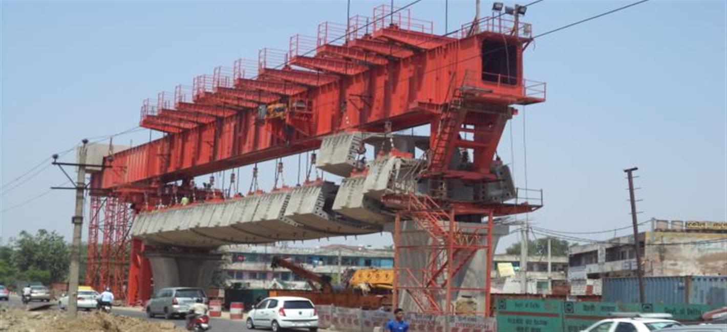
| 1 | Construction Methodology - The Construction Methodology is governed by site constraints, where there is a lackof availability of land for diversion of traffic. Therefore, stage construction is adopted for obligatory and viaduct spans. The concreting for piles is being carried out by means of Batching Plant / Ready Mixed Concrete and delivered by transport mixed and placed by tremie. Storage and stacking of any aggregate and sand etc., for the construction is prohibited within the project construction area. The superstructure is being constructed by Precast Segmental Construction in two parts i.e, Spine Beam and Cantilever Slab with Ribs. Further, Spine beam is also being constructed by Segmental Construction. |
|
|||
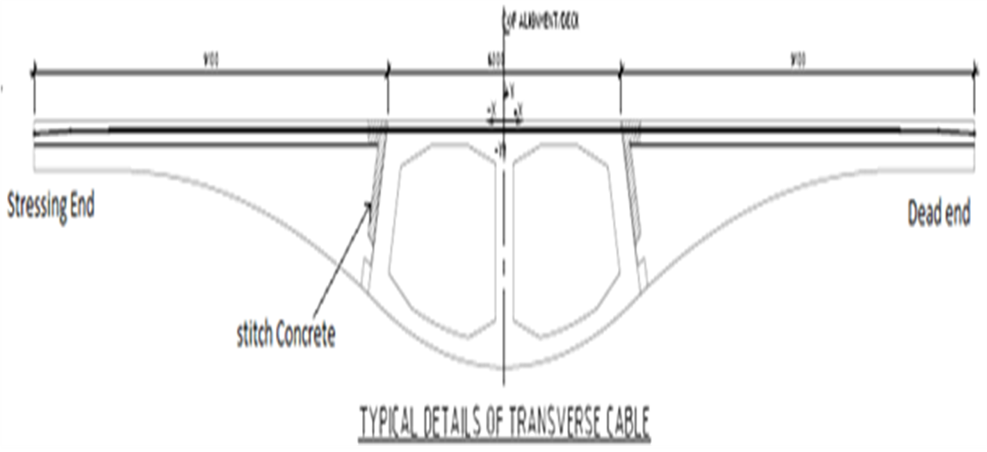
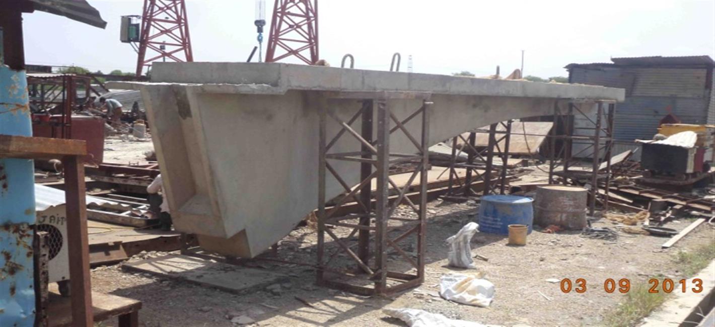
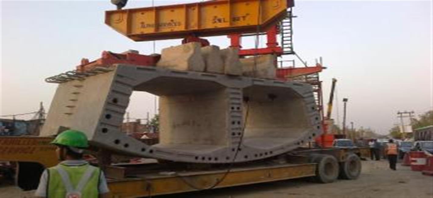
| 2 | Transportation and Erection of Segments - The maximum length of the segment is restricted to 3.0m for running section and 2.0m for diaphragm segments. The restriction of segment length is based on the assumption that the weight of the segment maintained is less than 50MT and easily transportable on low bed trailers. The precast segment are erected with overhead Launching Girder (L.G) with suspenders. All the segments of a single span are suspended from L.G, Aligned and joints glued. For this glue to be effective,temporary external prestressing is applied by Macalloy/Dywidag bars. Once the prestressing operation is completed the superstructure is lowered on temporary packing to support the spine beam. The L.G moves forward for erection of next span. In the next stage, the precast cantilever wings are erected by using a steel frame / portal structure supported on the already erected spine beam for lifting and aligning the precast cantilever segments. In case of curved span, cantilever slab is lifted on inner curve side first before erection of outer curve cantilever wing. Once the cantilever segments are erected longitudinal and vertical stitch joints between the cantilever slab and spine beam are carried out. This activity can be carried out for the entire cantilever wings (always a pair of wings) before application of transverse prestressing. Prestressingis also carried out individually as a pair of cantilever wings, once the in-situ stitch concrete attains minimum strength of 35Mpa. The cantilever segments are held in position using the steel frame structure till transverse prestressing operation is carried out. After completion of the transverse prestressing, the transverse joint between the cantilever wings is done. The super-structure spine segments are cast in a long-line/short line bed in the designated casting yard. The moulds of the soffit and webs are adjustable to achieve the prescribed geometry both vertically and horizontally. The joints between the segments are formed with a groove 10 mm deep. Other joints in the shuttering arrangement, if any are to be properly sealed and taped with suitable tapes to prevent grout loss. The segment joints are in the radial direction and the geometry of the superstructure is controlled by means of accurate control of the deck levels, which are to be measured at specified points. In order to verify the alignment at these points at the time of erection, suitable inserts are provided in the deck so that level measurements can be taken at the same point. Cantilever wings are cast separately and need not be match cast with spine segment. For proper finish in-situ stitch is done between the cantilever ribs with spine beam. To receive the precast wings / cantilever slab, at stub of 500(L) x 200(B) x 300(H) is provided at rib locations in the spine beam, which assists in seating of precast wings during connection with spine beam. Due to the curved natures of the soffit of the spine segments, the stacking of these segments is done in suitable designed saddles to maintain the stability of the segments. The segments can be stacked one above the other upto a maximum of 2 levels. These segments are transported on low bed trailers, with not more than one segment in each trailer. The segments are lifted from the bed, loaded on to the trailer and off loaded at the stacking area by means of a 100 Ton capacity mobile crane moving in the hoarded area of the construction. This shifting of the segments to the bridge site is done only in the night, with least disturbance to the traffic. The erection itself is done in the daytime if necessary, after obtaining necessary approval from the Traffic Police. |
|
Lessons Learnt / Take Aways
| S.No. | Description | Images | ||||
|---|---|---|---|---|---|---|
| 1 |
|
|