


Soil Anchors - Technology
Project Name : ADDITIONAL OFFICE COMPLEX FOR SUPREME COURT OF INDIA, PRAGATI MAIDAN, NEW DELHI
The additional office complex for Supreme Court of India is being constructed near Pragati Maidan, New Delhi on a land area measuring 12.19 Acres. The building complex is designed to be a state of art, environment friendly, centrally air conditioned office complex with all modern facilities. This new building complex will have five functional blocks of building and one service block. These blocks will be 4 to 9 storey high. Three level basements are provided covering all the blocks, with a car parking capacity of about 1800 cars. The foundation provided is raft foundation, with soil anchors provided below the raft to counter uplift due to water pressure. SITE FEATURES - The site is located near Pragati Maidan where “Appu Ghar ”was functioning earlier. The site is close to the Yamuna River and natural water table at the site is 2.5m below existing ground level. The depth of excavation is 15 m below ground level. The soil profile is indicated in Fig.1.Since the water table was very high and the excavation was very deep, to find suitable solution for retaining the earth for a height of 15 m was challenging.
68433 Lakh
Project Budget
08 Jan 2018
Start Date
08 Jan 2019
Completion Date
NEW DELHI
Location
Project Team / Contact Us
| S.No. | Name(Mr/Mrs) | Designation | Office Address | Office Number | Mobile Number | Email ID |
|---|---|---|---|---|---|---|
| 1 | B.B. Makkar | CPM, SCPZ |
TECHNOLOGY
ANCHORAGE -
Ground Anchorage- An installation that is capable of transmitting an applied tensile load to a load bearing stratum. The installation consists basically of an anchor head, free length and fixed length.
Permanent anchorage- An installation that is required to ensure the stability and satisfactory service performance of the permanent structure or execution being supported.
Temporary anchorage- An installation that is often used during the construction phase of a project to withstand forces for a known short period of time, usually less than 2 years.
Anchor- This term denotes to a component of the anchorage i.e. anchor head and free anchor length.
Anchor head- The component of a ground anchorage that is capable of transmitting the tensile load from the tendon to the surface of the ground or structure requiring support.
BOND -
Adhesion bond- The initially bond before slip that arises mainly from the physical interlocking,i.e. gluing, of the microscopically rough steel and the surrounding grout.
Friction bond- The bond that depends on the confining pressure ,the surface characteristics of the steel and amount of slip but is largely independent of the magnitude of the tendon stress.
Centralizer- Devices to maintain the tendon centrally in the borehole.
Characteristic strength- The value of the cube strength of grout or concrete(fcu) or the ultimate load of a prestressing tendon(fpu) constant below which not more than 5 % of the test results fall.
Creep- Creep is the movement of any part of the fixed anchor with time under constant tendon load. Creep can occur at both grout-tendon and the ground-grout interfaces.
LOAD -
Lock-off load- The load transferred to the anchor head immediately on completion of a stressing operation.
Proof Load- The maxm test load to which the anchorage is subjected during the initial stressing phase.
Proof load factor- The ratio of proof load to working load.
Working load- The safe load of the anchorage.
Apparent free tendon length- This is calculated from the load /elastic displacement data following testing.
Apparent free tendon length=A* Es *△/T
where
A, is the cross section area of the tendon;
ES is the manufacturer's elastic modulus for the tendon
Unit .
∆ is the elastic displacement of the tendon
equated to the displacement monitored at peak cycle
load minus the displacement at datum load, after
allowing for structural movement;
T is the peak cycle load minus datum load.
Anchor provides a downward force on raft and protecting it from the ground water up thrust.
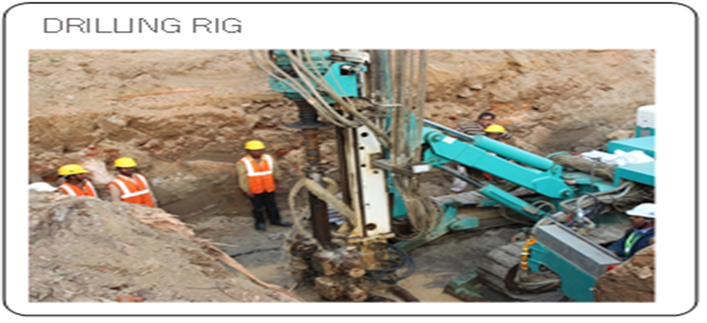
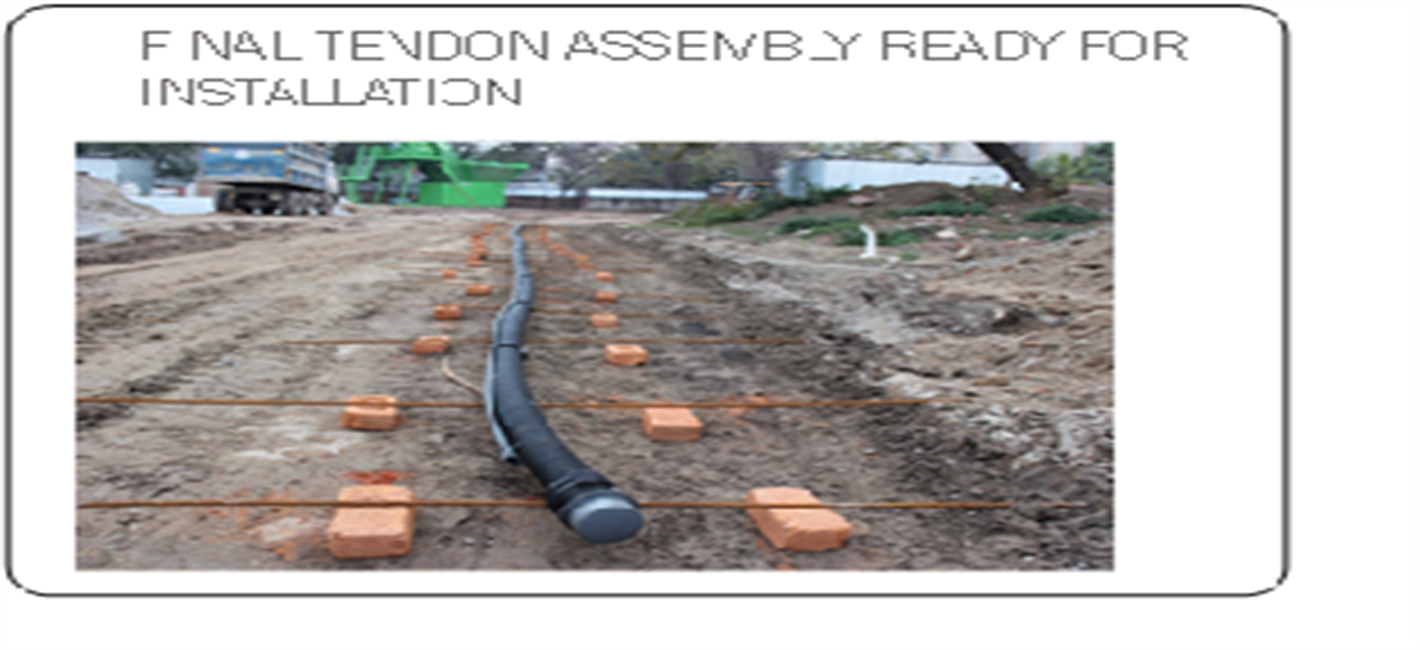
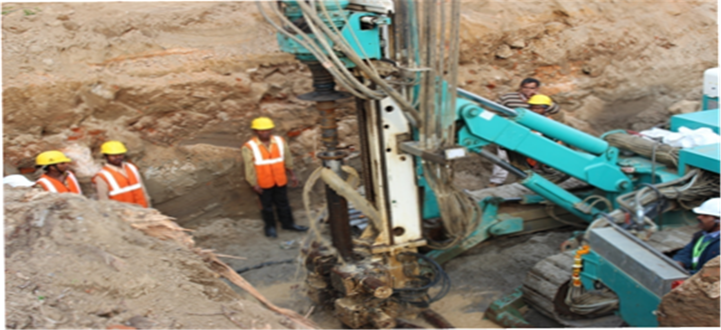
Implementation Strategy
| S.No. | Description | Images | |||
|---|---|---|---|---|---|
| 1 |
|
|
