Soil Nailing - Technology
Project Name : ADDITIONAL OFFICE COMPLEX FOR SUPREME COURT OF INDIA, PRAGATI MAIDAN, NEW DELHI
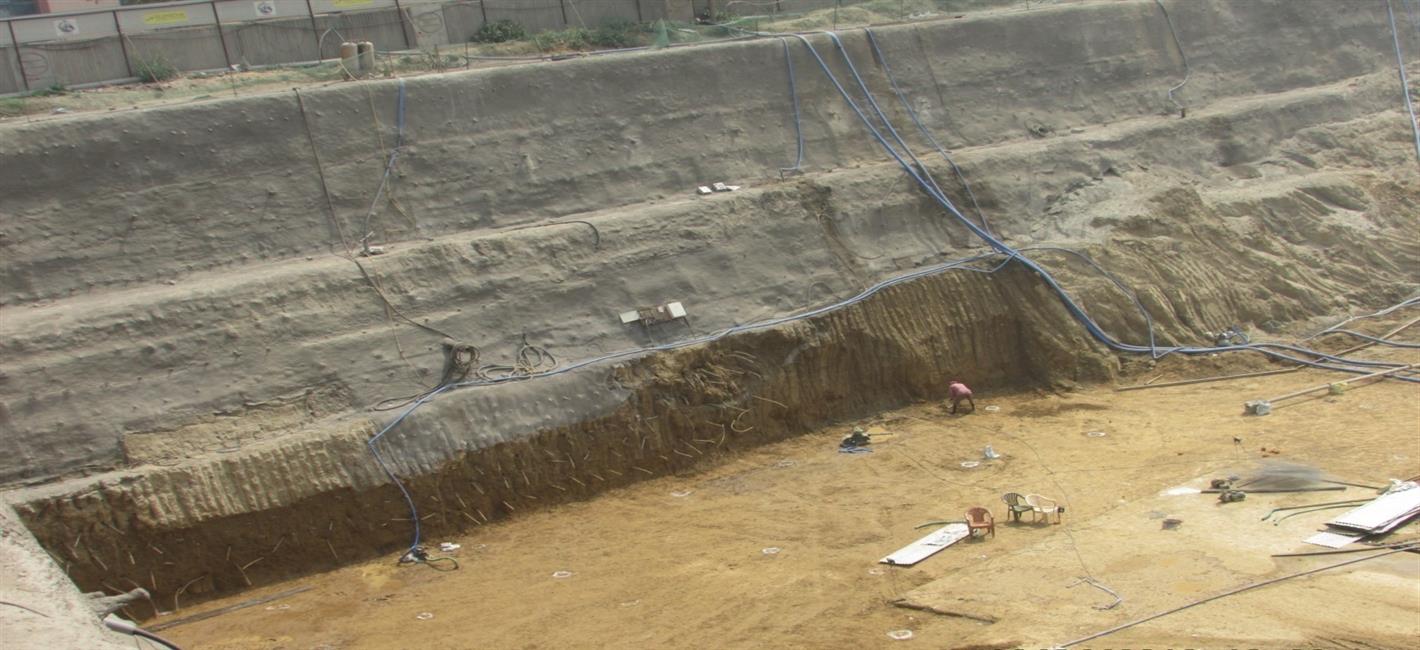
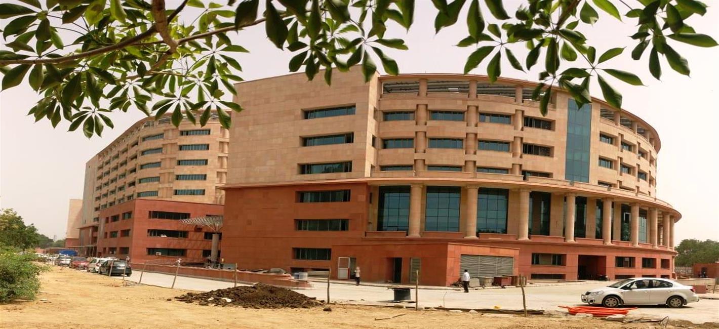
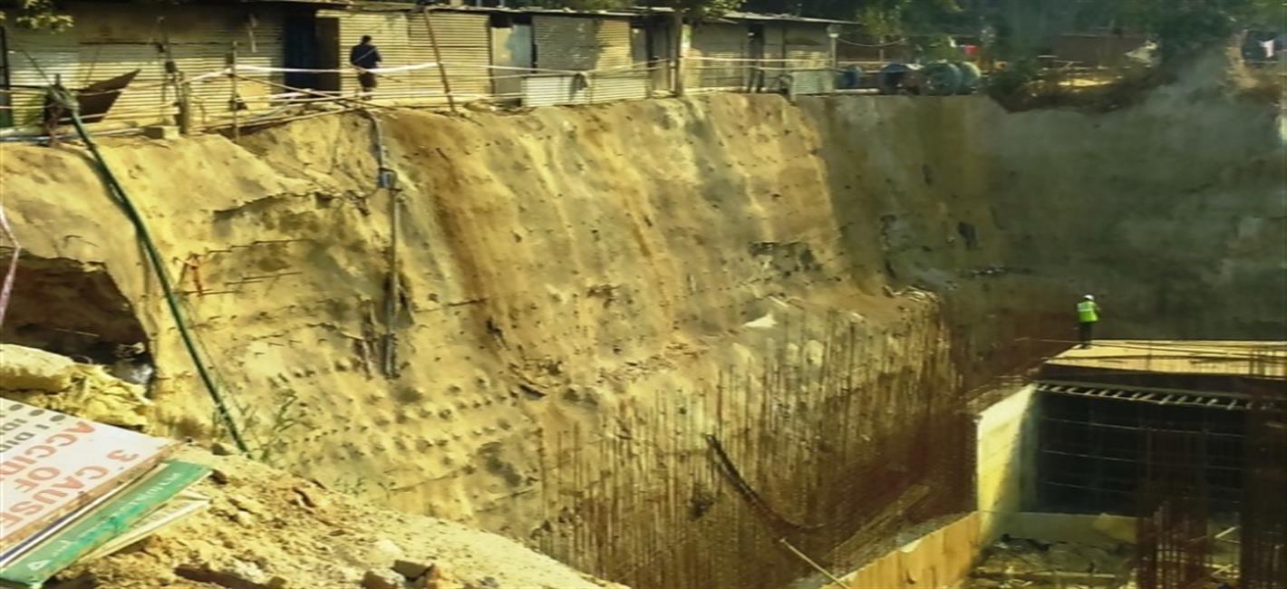
The additional office complex for Supreme Court of India is being constructed near Pragati Maidan, New Delhi on a land area measuring 12.19 Acres. The building complex is designed to be a state of art, environment friendly, centrally air conditioned office complex with all modern facilities. This new building complex will have five functional blocks of building and one service block. These blocks will be 4 to 9 storey high. Three level basements are provided covering all the blocks, with a car parking capacity of about 1800 cars. The foundation provided is raft foundation, with soil anchors provided below the raft to counter uplift due to water pressure. SITE FEATURES - The site is located near Pragati Maidan where “Appu Ghar ”was functioning earlier. The site is close to the Yamuna River and natural water table at the site is 2.5m below existing ground level. The depth of excavation is 15 m below ground level. The soil profile is indicated in Fig.1.Since the water table was very high and the excavation was very deep, to find suitable solution for retaining the earth for a height of 15 m was challenging.
88430 Lakh
Project Budget
01 Jan 2015
Start Date
15 Sep 2018
Completion Date
NEW DELHI
Location
Project Team / Contact Us
| S.No. | Name(Mr/Mrs) | Designation | Office Address | Office Number | Mobile Number | Email ID |
|---|---|---|---|---|---|---|
| 1 | B.B. Makkar | CPM, SCPZ | Supreme Court Project Zone, CPWD, Gate No-9, Pragati Maidan, New Delhi | 01123370796 | 9871600317 | cpmscp@gmail.com |
TECHNOLOGY
Soil nailing is a tempory earth retaining structure used for supporting vertical soil during excavation with limited setback conditions. This technique uses the pull out the strength of the reinforcement which should be more than the weight of the slip surface of the earth. Soil is reinforced with closely spaced steel nails()TMT bars and a surface is shot-created using steel wire mesh. The nailing is done at an angle as per design. Drainage pipes are also provided to act as weep holes.
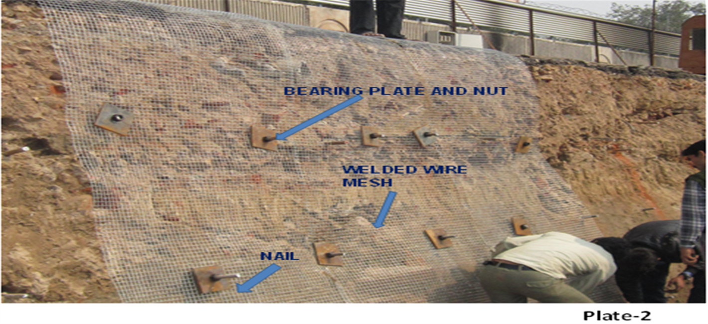
Elements of Soil nailing system -
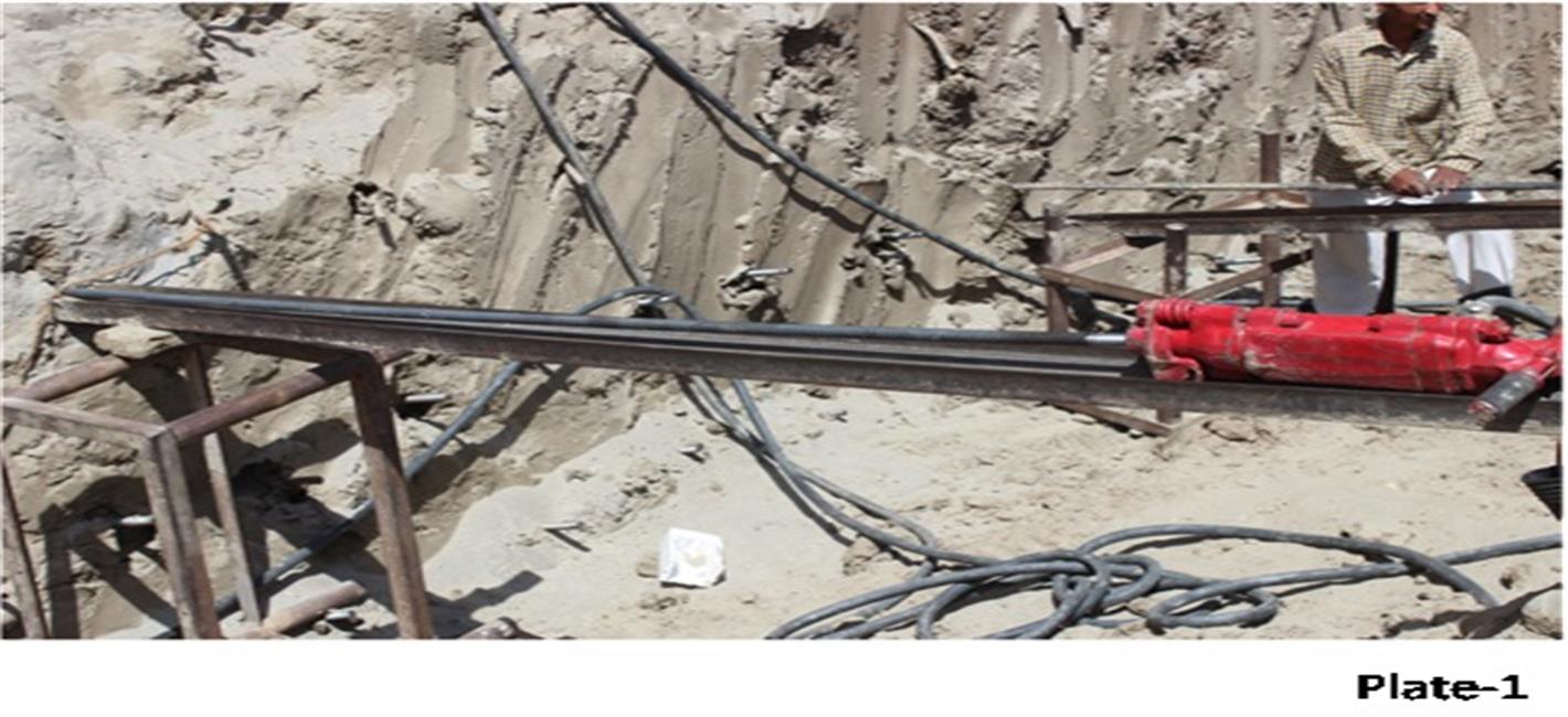
Nail Installation -
Nails are installed by driven process using pneumatic rammers with threaded end of the nail protruding outside the excavated surface. The threaded end is provided with steel plates which are tightened against the soil surface using steel nuts. The steel plates transfer bearing loads from the soil mass to soil nails and distributes the force at nail end to temporary shortcrete facing.
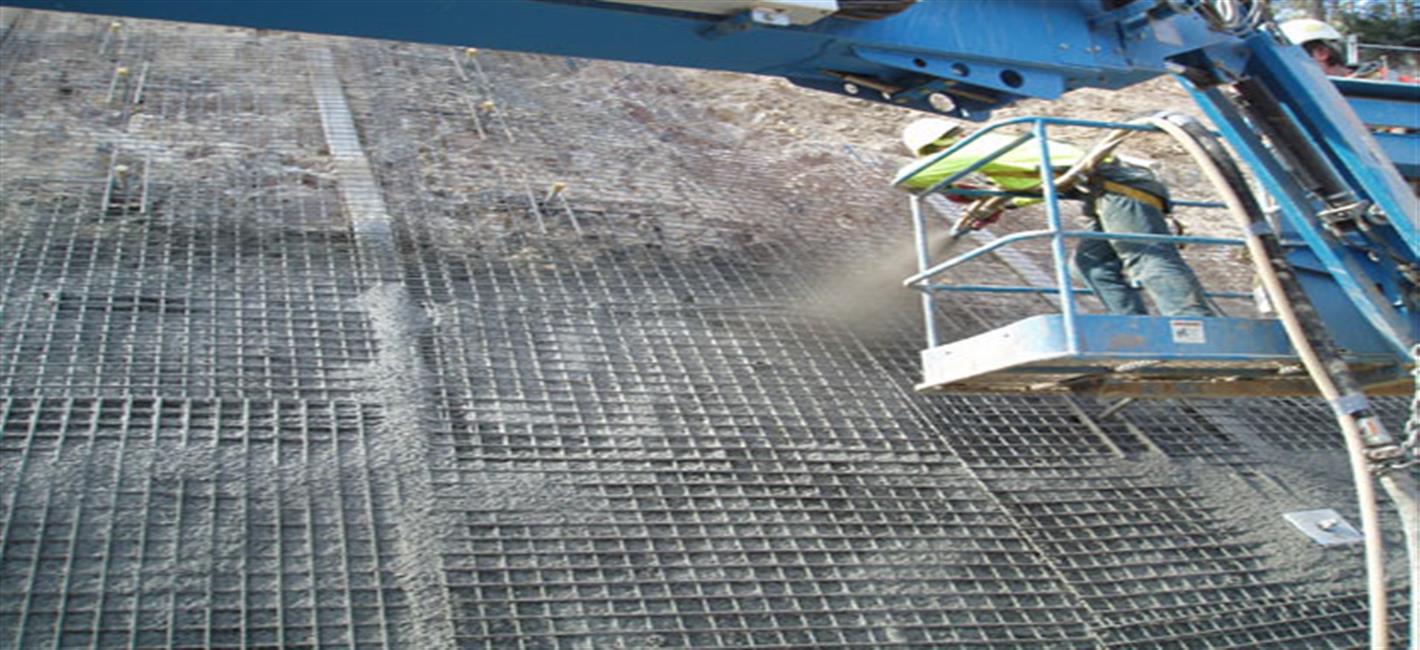
Fixing of Wire- Mesh -
Wire-mesh of appropriate gauge and size is fixed against the exposed surface of the slope and held in position by U- pins with the rear threaded part of the nail left outside.
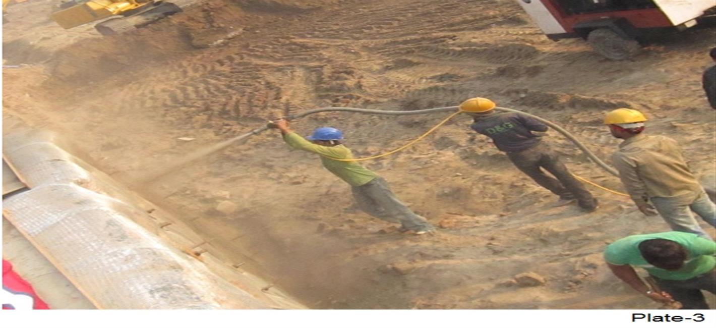
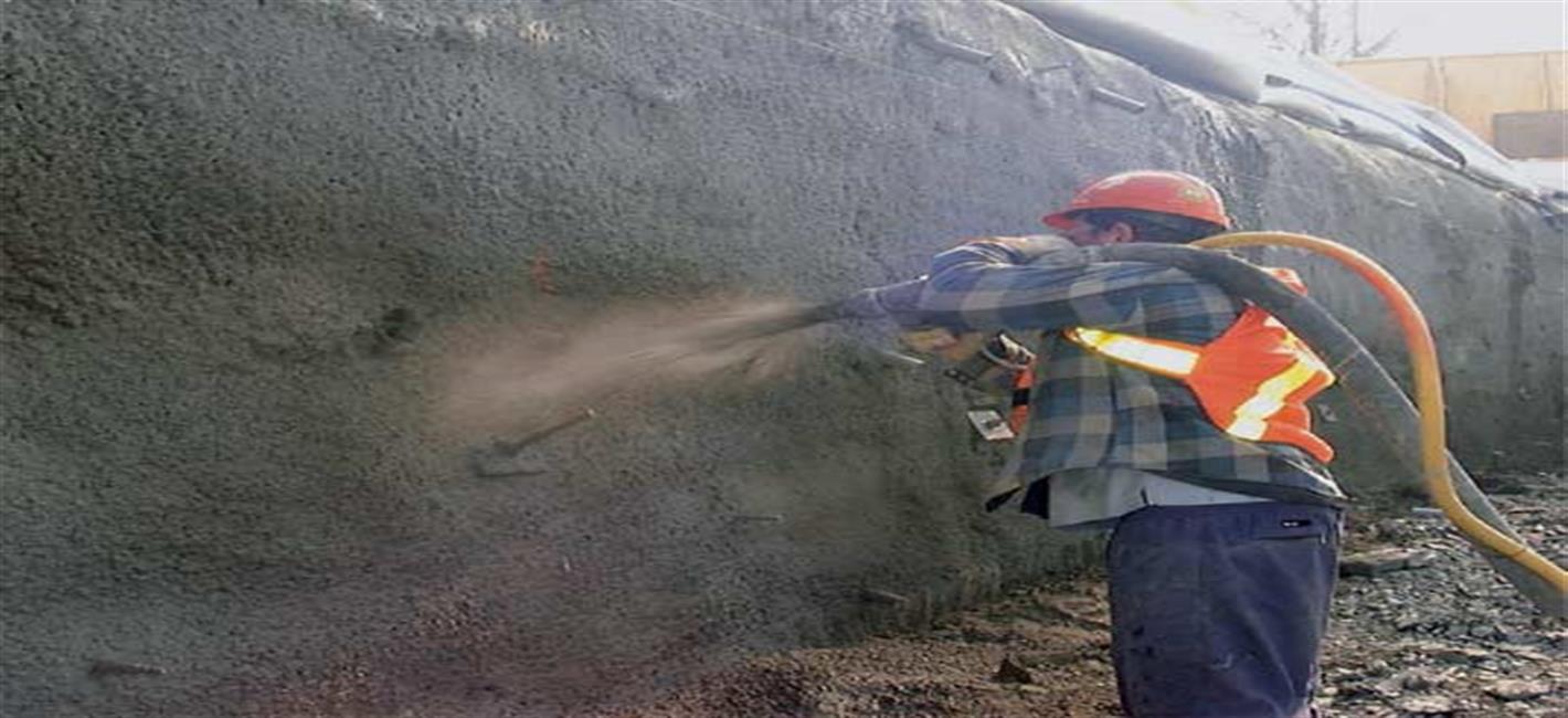
Shotcrete -
Shotcrete is applied perpendicularly into the exposed earth surface by means of pneumatic pressure over the weld mesh. The high speed shooting mortar produce self compacted cementious mortar at the facing. The ground surface is conditioned by trimming the slope surface reasonably smooth before receiving the shotcrete.
Subsurface Drainage System -
The drainage network consists of perforated drain pipe inserted into the soil mass to facilitate good drainage through soil mass and expedite quick disposal of rain water or sub- soil water. The drainage network is installed prior to shotcreting. Drainage pipes perforated at top and duly wrapped with geotextile is provided at suitable intervals to reduce the build of pore water pressure.
Cost comparison -
The methods available for temporary earth retaining are, (a) Diaphragm wall (b) H pile and wooden lagging (c) Sheet piling and (d) Touch piles & (e) Soil nailing
Approximate cost comparison (for depth 12 to 15 m) tabulated below-
Method |
Rate per sqm(approx.) |
Diaphragm wall |
25000-30000 |
H pile and wooden lagging |
12000-15000 |
Sheet piling |
20000-22000 |
Touch piles |
20000-25000 |
Soil nailing |
8000-10000 |
Implementation Strategy
| S.No. | Description | Images | ||||||
|---|---|---|---|---|---|---|---|---|
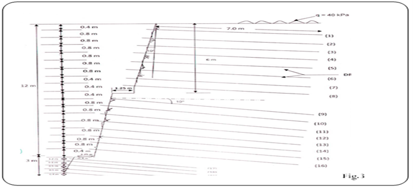
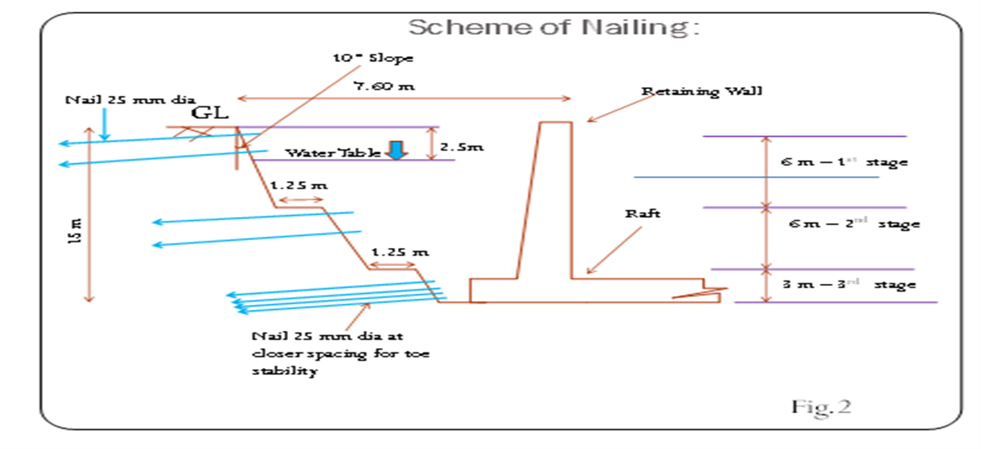
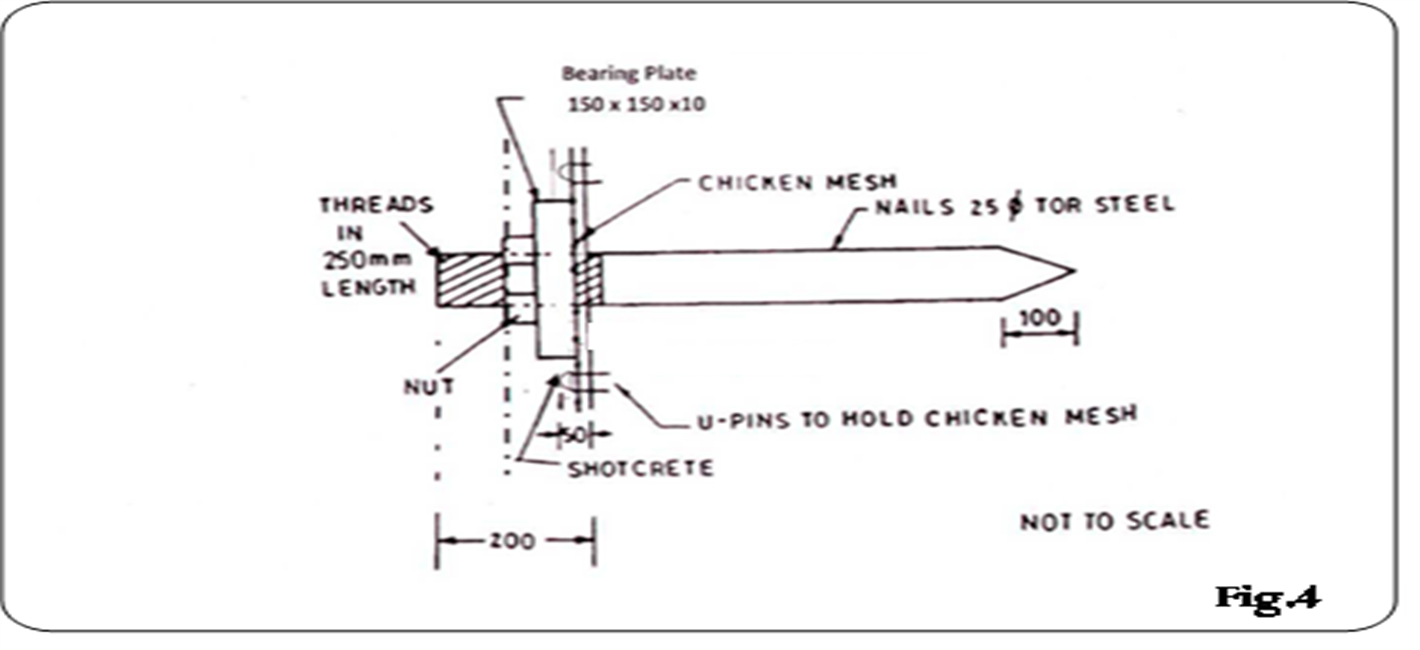
| 1 | Design Details - Soil at site is cohesion less soil. Pull out tests at different depths were carried out to assess frictional properties of soil. Average pull out resistance was found to be 0.50 t/m. Based on the pull out test results, the design for the same was developed. Following design details have been adopted for soil nailing - Nails - 25 mm dia TMT bar Nail length - 7 m up to 12 m depth & 5 m for 12 to 15 m depth. Nail spacing - First row of nail is at 0.4 m from top with 0.40 m c/c horizontal spacing and subsequent nails are at 0.80 m c/c horizontally and vertically. Slope of cutting - 10° with vertical. Welded wire mesh - 18 gauge ,aperture size 50 mm x 50 mm Bearing plate- 150 mmx150 mmx10 mm. Shotcrete - 75 mm thick with ratio 1 cement : 2 coarse sand: 2 pea size aggregate with w/c ratio 0.45 to 0.50 on sloped surface and 50 mm thick on horizontal berm. Drainage - 75 mm dia PVC pipe 7 m long with top half perforated wrapped with geo textile. One drainage pipe covers an area of 10 sqm of vertical surface. |
|
||||||
| 2 |
|
|